Article
citation information:
Cieślar,
K., Nowakowski, J. Knefel, T. Dynamic numerical stress analysis of a crankshaft of
internal combustion engine. Scientific
Journal of Silesian University of Technology. Series Transport. 2025, 127, 23-37. ISSN: 0209-3324. DOI: https://doi.org/10.20858/sjsutst.2025.127.2
Kacper CIEŚLAR[1], Jacek NOWAKOWSKI[2], Tomasz KNEFEL[3]
DYNAMIC NUMERICAL
STRESS ANALYSIS OF A CRANKSHAFT OF INTERNAL COMBUSTION ENGINE
Summary. Dynamic numerical
stress analysis of a crankshaft subjected to load at selected operational
points of a diesel engine is presented in this paper. The calculations and the
analyses were carried out for six values of engine rotational speed and for two
temperature values of engine structural elements. At each operating point of
the engine, the piston-crank system was loaded with maximal gas pressure force,
and additionally, inertia forces resulting from rotational speed of the
crankshaft were taken into consideration. The analysis was carried out to
obtain the distribution of the stress and to indicate critical areas where
concentration of the stress may occur. In addition, the analysis was extended
to other operational factors, such as the determination of the natural
frequency of vibrations and effects of maximal torque on torsion of the
crankshaft.
Keywords: crankshaft, FEM, ANSYS, numerical calculations, thermal calculations
1. INTRODUCTION
In
an internal combustion engine equipped with a piston-crank system, exhaust gas
pressure is converted into torque. Its direction, turn, and value of the load
are changing in time and can result in material fatigue. Phenomenon of material
fatigue is caused by cyclic changes in the stress; however, the course of this
phenomenon also depends on other factors, e.g., temperature
-
combustion
gas pressure force,
-
inertia
force,
-
friction
force.
The
pressure of gases in the cylinder changes, and is the highest at the beginning
of the expansion stroke.
The
inertia forces are present during the movement of masses in the piston-crank
mechanism, and their values are a function of the mass of its components and
accelerations of its individual elements.
All
masses of the crank mechanism can be grouped into:
-
the
masses concentrated in the center of the piston pin, and performing
reciprocating movement (piston with its pin and rings),
-
the
masses concentrated in the center of the crankpin of the crankshaft, performing
rotational motion (crankshaft),
-
the
masses of the conrod – performing complex moves (composed of reciprocating and
rotational moves). For this reason, masses of the conrod are replaced by a
system of two equivalent masses, and it is assumed that part of this mass is
concentrated in the center of the piston pin and performs reciprocating
movement, and the other part of the mass is concentrated in the center of the
crankshaft’s journal and performs rotational movement.
The
friction forces are considerably restricted by lubrication, and compared to the
others, such forces reach small values, and due to this, in the majority of the
analyses, these are neglected.
The
crankshaft must be robust enough to carry the load acting on it and ensure
reliable operation of the internal combustion engine. High-volume production of
components as the crankshaft requires its proper design and preliminary testing
before putting it into production. In such cases, numerical analyses allow
verification of the crankshaft in terms of strength as well as optimization of
its shape and dimensions, reducing manufacturing costs.
The
Finite Element Method is a type of numerical analysis allowing finding, in an
approximate and discrete way, a function describing the behavior of a given system (boundary problem) under certain
given conditions by dividing a complex problem (e.g., with complex shape) into
a finite number of elements (having a simpler geometry).
In
the study
In
the study [11] optimization of the crankshaft was performed in range of its
geometry and shape without effects on the structure of the cylinder block and
cylinder head of the engine. The optimization was carried out mainly on the
shape of counterweights, removing parts of material with slight changes in the
strength properties simultaneously allowing for a reduction in the weight of
the complete crankshaft by 4.37%.
The
numerical analysis [10] may also comprise strength analysis of the crankshaft
at several points of engine operation, and not only in extreme cases such as
the TDC and position for maximum tangential force. In this study, there were
also undertaken calculations for three different materials.
The
Finite Element Method also allows for predicting areas most susceptible to
damage. In the paper [1], the service life of the crankshaft of a six-cylinder
diesel engine of a truck was determined, modeling the
growth of fatigue cracks with the use of linear fracture mechanics. The results
of the calculations were confirmed by experimental tests.
The
results of the numerical calculations using the Finite Element Method are
implemented for analysis of various types of damage and to identify areas on
the crankshaft structure that are weak in terms of strength and which require
improvements. The following methodology was adopted in the article [8]: a model of the crankshaft is generated
in a computer system destined for advanced computer-aided design (CAD). The
Finite Element Analysis is next performed in the ANSYS system under static and
dynamic conditions to obtain changes in the stress at key areas. Data of the
engine, boundary conditions, and mechanical properties are taken into account
as the input data.
The
FEM [12] allows examination of an
effect of inclusions, e.g., manganese and sulfur, in
the structure of the steel of the crankshaft on its strength properties. In the
article, the structural model was precisely replicated from the real geometry
of a damaged crankshaft and divided into octahedral, tetrahedral elements
having the number of nodes equal to ten (ten-node tetrahedral). Analysis of
convergence of the mesh showed that values of reduced stress are convergent
when the size of the FEM element is 2 mm, and appears in the same areas as the
real damages. This will allow for predicting areas of probable damage.
Simulation
methods are also useful in the course of measuring of the crankshafts. In the
study [9], it was proposed a
measurement system developed on the basis of numerical calculations to support
the crankshaft with the use of flexible supports. This allowed elimination of
effects of reaction forces of the supports and thus elimination of deformations
of the crankshaft regardless of any possible deviations, e.g., concentricity of
the main journals. Values of the forces were calculated using the Finite Element
Method, based on these values, it was found that reaction forces change not
only on the supports but also in cases when the angular position of the
crankshaft is changing.
The
Finite Element Method enables thermal simulations as well. In the article [7],
there is presented analysis of displacements of the crankshaft's axis under
influence of temperature in a low-speed marine engine. Information about the
thermal displacements of the axis of the power transmission system is important
when determining the linearity of the crankshaft and its bearings. Thermal
displacements of the crankshaft calculated by numerical analysis have shown
a higher value than recommended by the manufacturer. The difference is not
large (less than 20%), but it may be a source of additional bending torque
and shearing force acting between the crankshaft and the cylinder block. The
calculations have shown that the manufacturer's assumption about parallel
displacement of the axis of the crankshaft is incorrect.
The
modeling may include analyses of low temperatures
[3]. In the article is presented a method to determine the shrinkages of
the main elements of the V6 engine (the crankshaft mainly) with a small
displacement for the cold phase at extremely low temperatures. The phenomenon
of thermal shrinkage generates mechanical wear of surfaces of rotating elements
in components of the engine. Based on calculations using the ANSYS program, in
the study it was proposed a suitable mathematical model enabling selection of
the fits at extremely low temperatures.
In
many cases, the phenomenon of vibrations can have decisive meaning in the
proper functioning of the crankshaft [5]. The vibrations may cause the
combustion engine to malfunction. The occurrence of phenomena of resonance may
cause an increase in amplitude of the vibrations, which may result in damage to
the crankshaft and related components. Regardless of the dynamics of the system
in which the engine operates, the greatest threat is caused by torsional
vibrations of the crankshaft.
In the
article is described the influence of selection of computational mesh on
results obtained during simulation of the crankshaft of a diesel engine.
Presented here, the methodology may be useful for performing calculations for a
new crankshaft. In the case of determination of mode of vibrations only, a
smaller mesh with a larger element can be used. It should be emphasized,
however, that the selection of elements of the mesh and its density must be
consistent with the geometric model. The smaller mesh elements, the more
accurate results, which has an effect on significant prolongation of the
calculations.
The
article [2] describes a study on the causes of premature failure of a
high-pressure diesel engine crankshaft. It was noted that all crankshafts
failed in the same part, namely the first crankpin. Dynamic analysis and finite
element modeling were conducted to determine the
stress state in the crankpin. The results of the finite element method showed
that the crankpin throw was the most susceptible to cracking. The Soderburg diagram for the analyzed
crankshaft indicated that the operational point, which signifies the values of
mean and alternating stresses in the critical crankpin throw area, was within
the safe zone. The results suggest that the failure was induced by overload,
with no signs of fatigue. It was recommended to reevaluate the design and production,
as well as optimize the crankpin throw rolling process. This recommendation was
adopted by the manufacturer, and since then, no further cases of failure have
been reported. The article concludes that the analysis of the crankshaft
failure helped eliminate fatigue as a cause and highlighted the need for
redesigning and reconstructing the project and production processes.
The
research [15] focused on analyzing various aspects
related to the failure of a diesel engine crankshaft. Initially, a visual
inspection of the damage was conducted, revealing signs of material fatigue at
the fracture site. Subsequently, material tests confirmed that the mechanical
properties of the crankshaft material were within the norm. However,
microcracks were found in the area of crack initiation, suggesting that the
damage could have been caused by material fatigue. Numerical analysis indicated
that the maximum stresses in the crack initiation area were relatively low
compared to the material's ultimate strength, suggesting that the fracture
could have been due to operational conditions. Moreover, modal analysis showed
that the second mode of vibration might be responsible for the damage to the
crankshaft in the crack initiation area. Based on these findings, several
corrective and improvement actions were proposed, such as increasing the fillet
radius on the connecting rods, further material testing, and implementing a
rolling process for the connecting rod fillets to prevent similar failures in
the future.
The
authors [4] proposed a methodology encompassing several key steps in the design
of crankshafts. Firstly, it utilizes advanced computer-aided design (CAD)
tools, such as CATIA, to precisely develop the crankshaft model. Next,
numerical analyses are conducted using ANSYS software, including stress
assessment, deformation analysis, and fatigue life prediction. In the
subsequent step, researchers perform design optimization aimed at reducing the
weight of the crankshaft with minimal impact on its strength and functionality.
The entire process is based on advanced computer engineering techniques,
allowing for precise analysis and optimization.
In
their conclusions, the authors emphasize the significance of integrating ANSYS
software in the design and development process of crankshafts. They indicate
that this tool enables higher efficiency, reliability, and performance in
internal combustion engines. Ultimately, this review suggests that the synergy
between ANSYS software and crankshaft development can lead to further
innovations in the automotive industry, paving the way for more sustainable and
efficient internal combustion engines in the future.
2. OBJECT OF
THE ANALYSES AND SCOPE OF THE NUMERICAL CALCULATIONS
The
crankshaft of an internal combustion engine plays an important role in
converting reciprocating motion of elements of the crank mechanism into
rotational motion. The complex state of the stress variable and significant
values of the load to which the crankshaft is subjected mean that this
component must be designed very carefully. Appropriate stiffness of this
component must be assured with possibly small dimensions. These dimensions
determine the size of the engine and therefore the possibilities of its
installation.
The
objective of this study was to determine the stress present in the crankshaft
operating at various rotational speeds. Efforts were taken to approach this
issue as broadly as possible. Therefore, in addition to the stress, the
displacements were determined, both for the load mentioned above and maximum
torsional torque; also, modal analysis of the crankshaft was performed.
The
crankshaft of a diesel engine to light road traction was analyzed.
The engine data is shown in Table 1.
Tab.
1
Technical
data of the internal combustion engine
|
Type of the engine |
Compression
ignition engine, CR system, turbo supercharger |
|
Layout/number of cylinders |
in – line engine /
4 |
|
Displacement |
1248 ccm |
|
Maximal power output |
55.2 kW at 4000 rpm |
|
Maximal torque |
190 Nm at 1500 rpm |
The
calculations and the analyses were performed for six values of engine
rotational speed: 1000, 2000, 3000, 3500, 4000, 4500 rpm. They cover the entire
operational range of engine speeds and enable assessment of an impact of the
load on the stress and the displacements. The calculations were performed for
two load cases. In the first one, it was assumed that for each of the
considered rotational speeds, the same force acts on the crankshaft,
constituting 75% of the maximum force loading the crank. There were
considered two temperature values of the engine's structural elements: 323 and
353K. The second case consists of the assumption that the crankshaft is loaded
on the cylinder axis by force resulting from the sum of the forces: gaseous and
inertia. The gaseous force was determined based on measurement of the pressure
in the combustion chamber. The maximum value of this force was taken for each
from the rotational speeds. In turn, the value of the inertia force was
determined for each rotational speed. Fig. 1 shows the summary value of the
force acting in the axis of the cylinder for the second loading case.
Fig. 1. Change of value of
the force acting on
the crankshaft for the second load case of the crankshaft
The
crankshaft was also subjected to the modal analysis. In combustion engines,
there are occurring periodically variable forces caused by changing pressure in
the cylinder and inertia forces. They result in torsional, flexural, and
longitudinal vibrations of the crankshaft and elements connected to the
crankshaft. In extreme cases, these vibrations can lead to resonance, and the
stress generated by the vibrations can cause damage to components of the engine
or their premature wear. Normally, analysis of torsional vibrations of the
crankshaft is carried out because such vibrations create the greatest risk in
case of the resonance. In order to estimate the natural vibrations of the
crankshaft, computational methods are used, which are based on the reduction of
the real vibrating system to a simpler equivalent system and use of one or more
analytical methods. However, the analysis of the torsional vibrations only does
not provide a complete picture of the issue, especially in the case of
multi-cranked crankshafts, where resonance may occur between the main journals.
To obtain a more comprehensive analysis, the Finite Element Method is used.
The
reduction of the real system, in the case of analytical methods, consists in
dividing the system into smaller parts and, next, determining their inertia and
torsional flexibility of the sections connecting adjacent parts. In order to
simplify the analysis, the division is often limited to individual crank
mechanisms, flywheels and auxiliary drives, main drives, vehicle drives, or
power take-off drives.
Simpler
analysis methods include methods for reducing the real crankshaft to
a single-mass, dual-mass, or three-mass equivalent system. To perform
analysis of the natural vibrations of the tested crankshaft after usage of the
reduction, the method of successive approximations, known as the Holzer method,
is also used. In this article, only the Finite Element Method was used.
Use
of the Finite Element Method to the issue of determination of natural frequency
of the crankshaft enables determination of all modes of vibrations, not only
torsional modes. The frequency analysis was performed using the ANSYS package.
The
following physical model supported in the main bearings and being able to
rotate freely was analyzed.
Supporting
conditions of the crankshaft in the main bearings were modeled,
allowing the main journals to move in direction of longitudinal axis.
After
carrying out the analyses, the properties of the steel from which the
crankshaft was made were determined: yield strength = 350 MPa, and ultimate
tensile strength = 420 MPa. Additionally, the following parameters were adopted
for calculations: density 7870 kg/m3, Young’s modulus = 210000 MPa,
Poisson's ratio = 0.3.
3.
CONSTRUCTION OF THE NUMERICAL MODEL
The
solid model of the crankshaft was created in the NX program. The model prepared
in this way and written in the format appropriate for the NX program (.stp) was exported to the ANSYS WORKBENCH software. The
calculations were prepared in the Transient Structural module used for dynamic
analysis of the system under the influence of time-varying loads. The mesh was
created using the Uniform function, which does not correct the shape of the
mesh because of dimensions and curvature of geometry. The mesh consists of
elements with 1 mm size; number of the nodes for a complete crankshaft amounts
to 6845909, and the number of the elements amounts to 1608812. Selection of an
appropriate size of the FEM element involves a compromise between accuracy
of the solution, available computational resources, and numerical stability.
Typically, smaller FEM elements lead to more accurate results because they
better model complicated shapes and gradients of areas. The size of the
elements was taken based on the previous experience of the authors [14],
striving to obtain accurate results of calculations because preliminary earlier
calculations, based on elements of various sizes, have indicated the need for
local thickening of the mesh up to 1 mm. In most cases the element size is a
compromise between the accuracy and time of the calculations. The mesh
generated on the model of the crankshaft is shown in Fig. 2.
Fig. 2.
Meshed model of the crankshaft
The boundary conditions, i.e., the force loading the
crankshaft and its support, were assumed in the following way: the crankshaft
was fixed using the cylindrical constraints in the crankshaft main bearing
journals, leaving the possibility of rotation of the crankshaft, while the
loading force was imposed on the surface of the crankpin in the angular range
from 0° to 120°. The boundary conditions as applied in the analyzed model are
presented in Fig. 3.
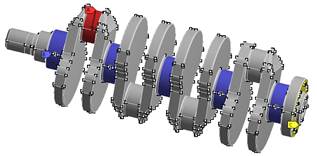
Fig. 3.
Boundary conditions applied to the crankshaft
4.
ANALYSIS OF RESULTS OF THE NUMERICAL CALCULATIONS
In the first step, numerical analyses were performed
applying load on the crankshaft with equal force, constituting approximately
75% of the maximal load on the crank. As expected, the highest values of the
stress and the deformations occur in the crankpin. Examples of calculation
results are shown in Fig. 4 (stress) and in Fig. 5 (deformations). The
deformations of the crankshaft fragments remain in the linear range, and for
better illustration, they are presented on scale of 1500:1.
Fig. 4.
Stress in the loaded crank for 1000 rpm
In the Fig. 6 are shown calculated values of
the displacements and the stress for temperature of 323K. The calculated values
of the displacements of the crankshaft operating at this temperature vary from
11.4 µm at 1000 rpm, to 10.47 µm at 4500 rpm, and therefore, by just over 8%.
The stress values for the temperature of 323K
change within a bigger range, i.e., from 83.96 MPa to 67.236 MPa, and hence, by
almost 20%.
Fig. 5.
Total deformations for 1000 rpm (in scale 1500:1)
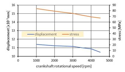
Fig. 6.
Displacements (blue color line) and stress (brown color line) of the crankpin
calculated for the temperature 323K
A similar character of the courses can be
observed for temperature of 353K (Fig. 7). However, in this case the
displacement values are higher - they change from 33.9 µm to 31 µm, i.e., by
8.5%. The stress calculated for the temperature of 353K shows a slightly higher
values and changes from 84.1 MPa to 68.1 MPa, i.e. by 19%.
In the successive step, calculations were made for
loading of the crankshaft with a force acting in the axis of the cylinder. The
results of the calculations for the loaded crankpin are presented in Fig. 8÷10.
And thus, together with increasing rotational speed, for
temperature of 293K, the displacement values decreased from 15.3 µm to 13.2 µm,
i.e., by 13.6%. However, the stress decreased only by 4.5% (from 75.4 MPa to
71.9 MPa, Fig. 8).
Together with increasing rotational speed, for the
temperature of 323K, the displacements value decreased slightly, from 13.4 µm
to 12.9 µm, i.e., by 3.7%. There was a significant change in the stress values
- from 86.4 MPa to 69.9 MPa, i.e., by 19% (Fig. 11).
In turn, for the temperature of 353K, increasing the
rotational speed results in decreasing the displacements value from 36.9 µm to
33.9 µm (by 8%), and the stress value to decrease from 87.3 MPa to 70.2 MPa,
i.e., by 19, 7% (Fig. 10).
In the course of the calculations, the values of the
stress and displacements at the free end of the crankshaft had taken negligible
values and were not subjected to the analyses.

Fig. 7.
Displacements (blue color line) and stress (brown color line) of the crankpin
calculated for the temperature 353K
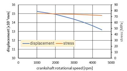
Fig. 8.
Displacements (blue color line) and stress (brown color line) of the crankpin
calculated for the temperature 293K
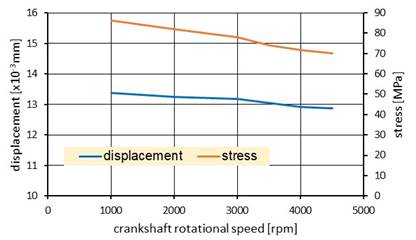
Fig. 9.
Displacements (blue color line) and stress (brown color line) of the crankpin
calculated for the temperature 323K
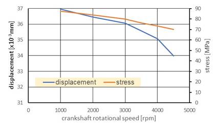
Fig. 10.
Displacements (blue color line) and stress (brown color line) of the crankpin
calculated for the temperature 353K
The results of the modal analysis are
presented in Table 2. The modes of vibrations were classified as a bending,
torsional and longitudinal ones, based on the dominant direction of the
displacement along the axis (X), or in transverse directions (Y, Z), or also in
the direction of the angle of rotation of the crankshaft. In the case of the
crankshaft, it is possible to talk only about the dominance of a specific form
of vibrations over the others, due to the complex, spatial nature of the
vibrations, especially in the case of the modes with a higher frequency.
Tab.
2
Natural
frequencies and modes of vibration
|
Mode |
Frequency [Hz] |
Modes of the
vibrations |
|
1 |
3918.4 |
Bending |
|
2 |
3918.6 |
Bending |
|
3 |
3922.8 |
Bending |
|
4 |
3922.9 |
Bending |
|
5 |
3933.3 |
Bending |
|
6 |
3934.3 |
Bending |
|
7 |
3946.8 |
Bending |
|
8 |
3947 |
Bending |
|
9 |
3950.6 |
Bending |
|
10 |
4261.6 |
Torsional |
|
11 |
4264.7 |
Torsional |
|
12 |
4266.2 |
Torsional |
|
13 |
4277.8 |
Torsional |
|
14 |
4278.3 |
Torsional |
|
15 |
4292.1 |
Torsional |
|
16 |
4292.4 |
Torsional |
|
17 |
4297.5 |
Torsional |
|
18 |
6006.5 |
Longitudinal |
|
19 |
6059.3 |
Longitudinal |
|
20 |
6087.9 |
Longitudinal |
|
21 |
6115.9 |
Longitudinal |
|
22 |
6442 |
Bending |
|
23 |
6442.3 |
Bending |
|
24 |
6443.4 |
Bending |
|
25 |
6444.9 |
Torsional |
|
26 |
6445.2 |
Torsional |
|
27 |
6447.9 |
Torsional |
|
28 |
6448.2 |
Torsional |
|
29 |
6449.8 |
Torsional |
|
30 |
6728.4 |
Longitudinal |
As can be noticed, all natural frequencies of
the existing types of vibrations lie outside the range of useful rotational
speeds of the analyzed crankshaft.
5.
CONCLUSIONS
Performed analyses constitute an attempt at a
complex method of proceeding, which enables determination of the stress and
displacements of the crankshaft of a modern, high-speed diesel engine. The
analyses have allowed determination of a role of calculated values in assessing
critical stress-strain of the material value and to identify areas that should
be designed with a particular care. The analyses have confirmed that
selection of the material is very important because it determines usage of
components having dimensions specified during the designing stage. After
carrying out calculations, it should be stated that analyzed crankshaft of the
engine was designed so that excessive stress values will not occur. Stiffness,
in spite of small overlapping of the crankshaft main bearing journal and the
crankpin, was ensured by using the appropriate thickness of walls. However,
special attention should be paid to transitions from the crankpin to the crank
arm. During the calculations, increased stress values were found in these
areas. In the opinion of the authors, after performing analysis of many cases,
increased stress values that appear in these areas result from peculiarities of
the FEM method. Hence, the need for completing calculations performed so far
with analyses that would take into account their special character.
The
analysis of the shaft calculation results shows that both displacements and
stresses decrease with increasing rotational speed. These changes are caused by
the unloading effect of the centrifugal force associated with the crankshaft,
which reduces the total value of the loading force.
The presented
stress values are reduced stresses and do not exceed the permissible values
specified for the crankshaft material.
Because displacement values decrease with
increasing crankshaft speed, the smallest journal-to-bearing clearance values
can be expected at low rotational speeds and high crankshaft material
temperatures. Please be advised that bearing housings may also experience
deformation as a result of elevated temperatures. The authors performed
additional analyzes of the crank bearing clearances and found that there was no
risk of bearing sticking in the considered range of rotational speeds and
temperatures.
From analysis of results of the calculations
of the crankshaft loaded with constant force is seen that temperature has a
small effect on values of the stress, but has important effect on values of the
displacements, which practically increase almost three times when temperature
changes from 323K to 353K. At a given operating temperature of the crankshaft,
a similar range of the changes in both the displacements and the stress takes
place (Fig. 11).
Fig. 11.
Percentage change of the displacements and stress calculated for various values
of temperature of the crankpin loaded with constant force acting on axis of
cylinder
Analyzing the results of the crankshaft calculations
loaded with force acting on axis of the cylinder, it can be noticed that the
stress increases with increasing temperature, while the most significant is
increase in the temperature in the range from 293 to 323K. Changes in the
displacements are ambiguous: after a slight decrease in temperature range of
293K÷323K, there occurs a significant increase in the range of 323K÷353K. At a
given operating temperature of the crankshaft, the changes both in the displacements
and the stress are different (Fig. 12), resulting from change in the crankshaft
load by a force acting on the cylinder axis (Fig. 1).
Fig. 12.
Percentage change of the displacements and stress calculated for various values
of temperature of crankpin loaded with a force acting on the cylinder axis
Using of the Finite Element Method enables a
comprehensive approach to the issue of natural vibrations of the crankshaft
because it allows for the determination of all possible modes of vibrations,
not only these of a torsional nature, as this takes place in the case of
analytical methods. Unfortunately, such an approach involves significant labor
required to prepare a computational model properly. However, owing to it,
it is possible to obtain a more complete picture of the crankshaft’s behavior
during vibrations, what is particularly important for more complex modes of
vibrations with higher frequencies. The crankshaft, due to its high stiffness
and method of its supporting, exhibits a dangerous phenomenon of resonance at
the level of 3918 Hz, which corresponds to rotational speed of 235080 rpm,
impossible to be achieved in operating conditions of the internal combustion
engine.
Numerical analyses using the finite element
method have proven useful for designing and analyzing structural components,
such as crankshafts. These calculations provide valuable information about the
behavior of crankshafts under various operating conditions and temperatures.
This information helps to optimize the shape and dimensions of crankshafts,
improving efficiency and reducing manufacturing costs.
These numerical calculations have proven
useful in designing and analyzing structural elements, such as crankshafts.
Despite the accuracy of the FEM method, each engine is tested intensively in
the prototyping phase for mechanical and thermal durability. However, one
should always consider changes in the material resulting from the machining
process in relation to the idealized computer model. This issue particularly
concerns elements exposed to friction and thermal loads. These processes enable
the final evaluation of the product.
References
1.
Aliakbari K., M. Imanparast, R.M. Nejad.
2019. „Microstructure and fatigue
fracture mechanism for a heavy-duty truck diesel engine crankshaft”. Scientia
Iranica 26(6): 3313-24.
2.
Farrahi G.H., S.M. H-Gangaraj, S. Abolhassani, F. Hemmati, M. Sakhaei. 2011. “Failure Analysis of a Four Cylinder Diesel
Engine Crankshaft Made From Nodular Cast Iron”. The Journal of Engine
Research 22: 21-28.
3.
Haba S.A., G. Oancea.
2015. “Studies on thermal contraction of crankshaft bearings under extreme low
temperatures”. Journal of Thermal Science 24(5): 496-501. DOI: https://doi.org/10.19206/CE-2019-443.
4.
Kumar S., Y. Mishra,
R. Sahu. 2024. “A review paper on design and development of crankshaft analysis
and modeling using ANSYS software”. International Journal of Progressive
Research in Engineering Management and Science 4(1): 106-9.
5.
Magryta P., K. Pietrykowski, K. Skiba. 2017. “FEM
simulation research of natural frequency vibration of crankshaft from internal
combustion engine”. ITM Web of Conferences 15: 07004.
6.
Mroziński S., R. Skocki. 2015. „Wpływ
temperatury na wyniki obliczeń trwałości zmęczeniowej”. [In
Polish: “Mechanicznej Developments In Mechanical
Engineering”]. Czasopismo naukowo-techniczne
– Scientific-Technical Journal 6(3): 43-55.
7.
Murawski L. 2016. “Thermal
displacement of crankshaft axis of slow-speed marine engine”. Brodogradnja 67(4): 17-29.
8.
Navathale T., N. Kharche, S. Shekokar,
D.P. Kharat. 2021. “A Review on Finite Element Analysis of the Crankshaft of Internal
Combustion Engine”. International Research Journal of Engineering and
Technology 6(Special Issue 01): 352-355. ISSN: 2456-236X.
9.
Nozdrzykowski K., Z. Grządziel, R. Grzejda,
M. Warzecha, M. Stępień. 2022. „An Analysis of Reaction Forces in Crankshaft
Support Systems”. Lubricants 10(7): 151.
10.
Sandya K., M. Keerthi,
K. Srinivas. 2016. “Modeling and stress analysis of crankshaft using Fem
Package Ansys”. International Research Journal of Engineering and Technology
03(01): 687-693.
11.
Shahane V.C., R.S. Pawar.
2017. “Optimization of the crankshaft using finite element analysis approach”. Automotive
and Engine Technology 2(1-4): 1-23.
12.
Tiana
L., N. Dinga, L. Liua, N. Xua, W. Guoa,
X. Wua, H. Xua, C.M. Wu. 2023. “Fracture failure of the
multi-throw crankshaft in a sport utility vehicle”. Engineering Failure
Analysis 145: 107036. DOI: 10.1016/j.engfailanal.2023.107036.
13.
Urbaś A., A. Harlecki,
J. Nowakowski, A. Byrski. 2013. „Analysis of dynamics of the piston-crank system of a selected internal
combustion engine with the use of the MSC.ADAMS and ANSYS software interface”. Combustion
Engines 154(3): 1076-1083. ISSN: 0138-0346.
14.
Wawrzyczek J., T. Knefel. 2019. “Stress analysis of the cylinder block of a small
compression ignition engine”. Combustion Engines 179(4): 259-263. ISSN: 0138-0346.
15.
Witek L., F. Stachowicz, A. Załęski.
2017. „Failure investigation of the
crankshaft of diesel engine”. Proceedings of the 2nd International
Conference on Structural Integrity, ICSI. 4-7 September 2017.
Funchal, Madeira, Portugal. Structural Integrity Procedia. 2017.
Received 05.12.2024; accepted in revised form 20.01.2025
![]()
Scientific Journal of Silesian
University of Technology. Series Transport is licensed under a Creative
Commons Attribution 4.0 International License