Article
citation information:
Zarenbin, V., Kolesnikova, T.,
Sakno, O., Ollo, V., Klimenko, V. Impact evaluation of piston rings mobility on a gas
passage in an internal combustion engine (ICE). Scientific Journal of Silesian University of Technology. Series
Transport. 2019, 104, 187-201.
ISSN: 0209-3324. DOI: https://doi.org/10.20858/sjsutst.2019.104.17.
Volodymyr ZARENBIN[1],
Tatiana KOLESNIKOVA[2], Olha SAKNO[3],
Vasyl OLLO[4], Victor KLIMENKO[5]
IMPACT EVALUATION OF PISTON RINGS MOBILITY ON A
GAS PASSAGE IN AN INTERNAL COMBUSTION ENGINE (ICE)
Summary. To estimate the effect of the axial movement of piston rings in the piston
grooves on the blow-by in the internal combustion engine (ICE) by an
experiment- calculated method. This contributes to the development of practical
recommendations for the further improvement of the engine ring seal designs. Abstract theorems were used when modelling the effect of the axial movement
of piston rings in the piston grooves on the blow-by in an ICE. They are based
on the fundamental theory of heat engines, thermodynamics and hydraulics. The
ICE running was analysed using design-theoretical research
methods. The effect of the axial
movement of piston rings in the piston grooves on the blow-by in the ICE was established. This creates
prerequisites for a more accurate assessment of their sealing capacity and for ways to further improve them.
Calculated dependences for computing the blow-by depending on the positional relationship of
the rings in the piston grooves were obtained. The dependences of gas escapes on the engine crankshaft
speed were obtained, which is especially
important for idling modes by which one can judge the dynamic stability of the
ring seal and solve the problems of improving its service properties. The calculated dependences for
evaluation of the blow-by depending on the positional relationship of the rings
in the piston grooves and their respective possible gas flows in the ring seal were obtained for the first time. The practical method for estimating
the dynamic stability of the ring seal by decencies of gas escape on the
crankshaft rotation speed in ICE was proposed.
Keywords: ICE ring seal, piston ring
mobility, calculation of gas escape.
1. INTRODUCTION
The internal combustion engines (ICE) of trucks
used in the mining industry are one of the critical units with expensive
repairs. The ICE requires a preliminary diagnosis, which assesses the technical
condition of both the engine and the truck as a whole.
The ICE generate vibrations and noise during operation. They
can also be successfully used for diagnostic purposes. Such methods have been
increasingly used in recent years [3-8,10,16,18,23,24].
The technical condition of the parts of the
cylinder-piston group (CPG) can be determined by gas escape in the ICE.
The modern development of the high-speed
ICE is the way to improve their technical, economic and environmental
performance. This predetermines [1,2,9,15,20]:
a) the expansion of research and
development projects on the further design and technological improvement of
parts of the CPG of the ICE
b) the choice of optimal
conditions for interfacing their contacting surfaces
c) improving the quality of used materials
Piston rings (PR) are the most
high-wear parts of the CPG, thus, the issues of improving their performance and
reliability are of current importance when creating prospective engines used in
the mining industry.
The main factors that
determine the normal running of the ICE are the condition of coupling of
surfaces of the compression rings with the cylinder wall and their ends with
the top and bottom planes of the piston grooves. This is connected with the
sealing of the combustion chamber and prevention of a considerable blow-by in the engine
case.
Gas escapes through the gaps
in the parts mating of the CPG, break the oil film and increase wear which, in turn, increases gas escape.
This furthers the seizing of the piston rings, increase in oil consumption and fuel, and
smoking. The final result is jamming and engine trouble.
A wide variety of factors
influencing the operation of the PR complicates analysis and generalisation of the experimental data and
development of general principles of the theoretically substantiated choice of
designs of the ICE ring seal. The solution of this issue could be based on the account of
the totality of the main phenomena that determine the operability of CPG and PR
parts.
Numerous papers cover the experimental and theoretical
study of the PR operation. In [12] it was found that the
hydrodynamic friction increased with the initial wear of the PR in conditions
of increasing minimum thickness of the oil film. This contributes to the fact
that the PR can remain operational during the entire service life. Hydrodynamic
friction for high rings can be reduced using a narrow parabolic profile, which is impossible for narrow rings.
A laser fluorescence system
was developed to visualise
the thickness of the oil film between the PR and the cylinder wall of the
running gasoline engine through a small optical window installed in the
cylinder wall. The results show significant differences in the profiles of the
thickness of the lubricant film for the ring seal if the lubricant
deteriorates, which affects the ring friction and, ultimately, fuel economy [14].
The diagnostic methodology can
effectively determine the control of the condition of the PR in accordance with
the characteristics of combustion [13].
The calculation of the gas
flow through the ICE ring seals with regard to the piston rings dynamics allows
diagnosing the engine technical condition.
2D CFD model is used to study
the effect of the ring seal design on the friction process, oil consumption and
oil flow. Calculations of the piston rings dynamics were carried out on the assumption of
forces balance [11].
Methods and devices to study
mechanical friction losses were developed [19]. A simplified floating liner
method was used and the test equipment was developed to fill the gap in between
the full floating liner engine and the typical component bench test equipment.
The purpose of this research [17] was to study the potential of the
laser oil pockets new design so as to improve the piston rings lubrication. These pockets
make it possible to achieve significant friction reduction by using appropriate
geometric parameters [7,8,10,24].
Presently, there is a wide range of
solution of the PR reliability and operating life problems. However, the
dynamics of the parts of the CPG are not sufficiently considered. In
particular, this is the PR movement in the piston grooves. This is connected
with the engine running, where
all piston rings moving are
difficult to measure; there are no theoretical dependencies that link the PR
mobility in the piston grooves with gas escapes through the ring seal.
2. DYNAMIC ANALYSIS OF GAS FLOW
THROUGH THE ICE RING SEAL
In general, the problem of the
gases flow through the volumes on lands and piston ring grooves is quite
complicated. However, it can be simplified if the following experimental and
theoretical justifications of assumption are introduced:
a) the gas flow process is taken
to be quasi-stationary
b) the areas of the flow passage
between the PR, the piston and the cylinder liner should be replaced by the
equivalent area of the flow passage of the piston-ring lock
c) geometric relationships in the ring seal can only be
changed due to axial unloading of the rings and their subsequent separation
from the bearing area of the groove
In this paper, the problem is considered on the
example of the ring seal consisting of three rings in various cases of their
relative position in the grooves, which received experimental confirmation in
the paper.
The principal features of the
adopted model were that
it takes into account the throttling effect of the upper fascia of the piston
and the change in the areas of the flow sections and the volume of the annular
spaces due to the movement of the rings in the grooves.
It is accepted that the
separation of the rings from the support surfaces of the groove in the
direction of the piston axis occurs at the moments when the sum of the forces
from the gas pressure ![]() , the inertia of the ring
, the inertia of the ring ![]() and the friction
and the friction ![]() are zero, which means
are zero, which means
![]() (1)
(1)
The theoretical studies were
based on the differential equations of mass and energy balances, as well as the
criterion equation of heat exchange for the gases flow in micro-gap channels.
For the second and third piston grooves, the gases flow was accepted to be
isothermal with a gas temperature equal to the arithmetic average of the
temperatures of the piston grooves and the cylinder liner.
As a result of the dynamic
calculation the total forces that act on the piston rings, as well as various
cases of their positional relationship in the grooves and their corresponding
possible gas flows in the ring seal were identified.
Blow-by m through the PR leakiness was calculated by the formula:
 (2)
(2)
where ![]() – discharge coefficient
and flow section between volumes on lands and the piston ring grooves [m2];
– discharge coefficient
and flow section between volumes on lands and the piston ring grooves [m2];
![]() – speed
function, which depends on the pressure ratio;
– speed
function, which depends on the pressure ratio; ![]() ,
, ![]() – pressure [Pa] and gas
temperature in the grooves [K];
– pressure [Pa] and gas
temperature in the grooves [K]; ![]() – gas constant, R=287 [J/(kg.K)];
– gas constant, R=287 [J/(kg.K)];![]()
![]() – time [s].
– time [s].
The following formulas to
calculate the pressures and the blow-by in various cases of the positional
relationship of the rings in the piston grooves were obtained.
2.1. Case 1 of the positional
relationship of the rings in the grooves of the piston, when ![]() ,
, ![]() and
and ![]()
The initial equations
for the calculation are the mass and energy balance Equations. Cylinder
pressure (![]() ) is calculated
) is calculated
![]() (3)
(3)
![]() (4)
(4)
where ![]() and
and ![]() – change of
elementary mass and internal energy of gases in the top groove during
– change of
elementary mass and internal energy of gases in the top groove during ![]() ;
; ![]() and
and ![]() – the
elementary mass and enthalpy of gases which flow into the top groove out of the
cylinder during
– the
elementary mass and enthalpy of gases which flow into the top groove out of the
cylinder during ![]() ;
; ![]() and
and ![]() – the
elementary mass and enthalpy of gases which flow from the top groove to the
second groove during
– the
elementary mass and enthalpy of gases which flow from the top groove to the
second groove during ![]() ;
; ![]() – the
elementary quantity of heat that is transferred (or perceived) gases
surrounding surfaces of CPG parts during
– the
elementary quantity of heat that is transferred (or perceived) gases
surrounding surfaces of CPG parts during ![]() .
.
The Equation (4) is
differentiated. The Equation (3) is substituted into this equation. As a
result, the following equation has the form:
![]() (5)
(5)
Internal energy of gases
is determined ![]() (
(![]() – mass isochoric heat capacity of gases at constant
volume V in the ring groove); the
enthalpy of gases is determined
– mass isochoric heat capacity of gases at constant
volume V in the ring groove); the
enthalpy of gases is determined ![]() (
(![]() – mass isobaric heat capacity of gases at constant
volume V in the ring groove); gas
state is determined
– mass isobaric heat capacity of gases at constant
volume V in the ring groove); gas
state is determined ![]() . The following equations are used
. The following equations are used
![]() and
and ![]() (6)
(6)
where ![]() – heat
exchange coefficient from gases to surfaces of the cylinder and the piston
– heat
exchange coefficient from gases to surfaces of the cylinder and the piston
[![]() ];
]; ![]() – cooling
surface temperature [K].
– cooling
surface temperature [K].
The equation is
transformed and as a result has the following form
 (7)
(7)
where ![]() ;
; ![]() ;
; ![]() ;
; ![]() ;
; ![]() ;
; ![]() ;
; ![]() ;
; ![]() – volume of
ring groove I [m3];
– volume of
ring groove I [m3]; ![]() ,
, ![]() – average
temperature of the piston head [K];
– average
temperature of the piston head [K]; ![]() – the
determining gas temperature [K];
– the
determining gas temperature [K]; ![]() – gas
pressure in the minimum section of the jet [Pa];
– gas
pressure in the minimum section of the jet [Pa]; ![]() – gas
pressure in the cylinder [Pa];
– gas
pressure in the cylinder [Pa]; ![]() – average
temperature of the piston head and cylinder liner [K].
– average
temperature of the piston head and cylinder liner [K].
The calculation of the
blow-by when the sum of the forces acting on the rings ![]() is positive and the gases
pressure decreases from the top PR to the bottom (Fig. 1) is the following:
is positive and the gases
pressure decreases from the top PR to the bottom (Fig. 1) is the following: ![]() ,
, ![]() and
and ![]() with
with ![]() .
.
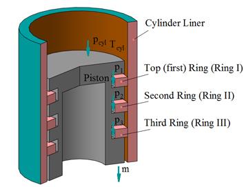
![]() – mass gas
escape;
– mass gas
escape; ![]() ,
, ![]() ,
, ![]() – gas
pressure in annular piston cavities I, II and III
– gas
pressure in annular piston cavities I, II and III
Fig. 1. Case 1 of the
positional relationship of the rings in the grooves of the piston, when ![]() ,
, ![]() and
and ![]()
Then
 (8)
(8)
where рН – gas pressure in the crankcase
[Pa]; ![]() – the
adiabatic coefficient of gas per ring I;
– the
adiabatic coefficient of gas per ring I; ![]() – the
adiabatic coefficient of gas in the cylinder;
– the
adiabatic coefficient of gas in the cylinder; ![]() – gas
temperature in the cylinder [K];
– gas
temperature in the cylinder [K]; ![]() – heat
receiving surface area [m2];
– heat
receiving surface area [m2]; ![]() – mass heat
capacity of gases at constant volume in the ring groove I [
– mass heat
capacity of gases at constant volume in the ring groove I [![]() ];
]; ![]() – mass heat
capacity of gases at constant volume in the cylinder [
– mass heat
capacity of gases at constant volume in the cylinder [![]() ]
]
and
![]()
![]()
![]()
![]() (9)
(9)
Pressure difference in
the heat zone of the piston, subject to maintaining the constancy of the gases
velocity is determined
![]() (10)
(10)
where р – gas pressure in the annular gap between
the heat zone of a piston and cylinder; W
– average consumed gases velocity; ![]() – gas
density;
– gas
density; ![]() – the
equivalent diameter of the channel in the form of gap;
– the
equivalent diameter of the channel in the form of gap; ![]() – width of
a gap;
– width of
a gap; ![]() – movement gas
resistance coefficient.
– movement gas
resistance coefficient.
The Equation (10) is
integrated on condition that ![]() (
(![]() is Reynolds number).
is Reynolds number).
Then
![]() (11)
(11)
where ![]() is gas density in the minimum
section of the jet and
is gas density in the minimum
section of the jet and  .
.
Then
![]() (12)
(12)
Equations (11) and (12)
are taken into consideration. As a result, the following equation is obtained
 (13)
(13)
where ![]() – speed loss coefficient.
– speed loss coefficient.
The equation for the second and third grooves (m = 2, 3, ![]() =
=![]() ) is the following:
) is the following:
 (14)
(14)
where ![]() is the adiabatic
coefficient in m-th groove;
is the adiabatic
coefficient in m-th groove; ![]() is gas
temperature in m-th groove [K].
is gas
temperature in m-th groove [K].
Then Formula (2) is the
following:
![]() (15)
(15)
where ![]() – Discharge
coefficient and flow section over PR III [m2];
– Discharge
coefficient and flow section over PR III [m2]; ![]() and
and ![]() – Pressure [Pa] and gas
temperature in ring groove III [K].
– Pressure [Pa] and gas
temperature in ring groove III [K].
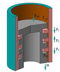
Pressure in
ring groove II has the following by Formula (16) if ![]() <
<![]() <
<![]() and
and ![]() >
>![]() (Fig. 2). The
Formula (16) is following:
(Fig. 2). The
Formula (16) is following:
 (16)
(16)
where ![]() is a volume of
ring groove II [m3];
is a volume of
ring groove II [m3]; ![]() is determined by the Formula (4)
is determined by the Formula (4)
with m = 3; ![]() – Volume of
the ring groove III [m3]
– Volume of
the ring groove III [m3]
and
![]() =
=![]()
![]()
![]()
![]()
![]()
![]()

Fig. 2. Case of the
positional relationship of the rings in the grooves of the piston, when ![]() <
<![]() <
<![]() and
and ![]() >
>![]()
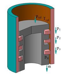
2.2. Case 2 of the
positional relationship of the rings in the grooves of the piston, when ![]() ,
, ![]() and
and ![]()
The calculation of the
blow-by if the sum of the forces acting on the ring I is positive and on the
rings II and III is negative (Fig. 3, a) is the following:
![]() ,
, ![]() ,
, ![]() with
with ![]() .
.
Then
![]() is determined by the Formula (8);
is determined by the Formula (8);
![]() is determined by the Formula (14) with m = 2;
is determined by the Formula (14) with m = 2;
![]() =
=![]() .
.
When ![]() <
<![]() >
>![]() (Fig. 3, b):
(Fig. 3, b):
![]() (17)
(17)
where ![]() is gas pressure
in the in the ring groove II [Pa]
is gas pressure
in the in the ring groove II [Pa]
![]()
![]()

a) b)
Fig. 3. Case 2 of the
positional relationship of the rings in the grooves of the piston, when:
a) ![]() ,
, ![]() and
and ![]() ; b)
; b) ![]() <
<![]() >
>![]()
Then Formula (2) is the
following:
 (18)
(18)
where ![]() is gas
temperature in the ring groove II [K].
is gas
temperature in the ring groove II [K].
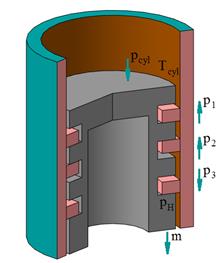
2.3. Case 3 of the
positional relationship of the rings in the grooves of the piston, when ![]() ,
, ![]() and
and ![]()
The calculation of the
blow-by if the sum of the forces acting on the ring I and III is positive and on the
ring II is negative (Fig. 4, a) is the following:
![]() ,
, ![]() and
and ![]() with
with ![]() .
.
a)
b)
Fig. 4. Case 3 of the
positional relationship of the rings in the grooves of the piston, when:
a) ![]() ,
, ![]() and
and ![]() ; b)
; b) ![]() =
=![]() >
>![]()
Then ![]() is determined by the Formula (8)
is determined by the Formula (8)
 (19)
(19)
where ![]()
When ![]() =
=![]() >
>![]() and
and ![]() =
=![]() (see Fig. 4, b):
(see Fig. 4, b):
 (20)
(20)
Then Formula (2) is the
following:
 (21)
(21)
2.4. Case
4 of the positional relationship of the rings in the grooves of the piston,
when ![]() ,
, ![]() and
and ![]()
The calculation of the
blow-by if the sum of the forces acting on the ring I and II is negative
and on the ring III is positive is the following (Fig. 5):
![]() ,
, ![]() and
and ![]() with
with ![]() .
.
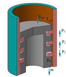
Fig. 5. Case 4 of the
positional relationship of the rings in the grooves of the piston, when ![]() ,
, ![]() and
and ![]()
Then
 (22)
(22)
2.5. Case 5 of the
positional relationship of the rings in the grooves of the piston, when ![]() ,
, ![]() and
and ![]() with
with ![]() and
and ![]() =
=![]()
The calculation of the
blow-by if ![]() ,
, ![]() and
and ![]() with
with ![]() and
and ![]() =
=![]() (Fig. 6) is the
following.
(Fig. 6) is the
following.
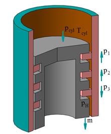
Fig. 6. Case 5 of the
positional relationship of the rings in the grooves of the piston, when ![]() ,
, ![]() and
and ![]() with
with ![]() and
and ![]() =
=![]()
Then ![]() is determined by the Formula (15) with
is determined by the Formula (15) with ![]() =
=![]() ;
; ![]() =
=![]() and
and ![]() =
=![]() .
.
2.6. Case 6 of the
positional relationship of the rings in the grooves of the piston, when ![]() ,
, ![]() and
and ![]() with
with ![]() ,
, ![]() =
=![]() and
and ![]() =
=![]()
The calculation of the
blow-by if ![]() ,
, ![]() and
and ![]() with
with ![]() ,
, ![]() =
=![]() and
and ![]() =
=![]() (Fig. 7) is the
following.
(Fig. 7) is the
following.
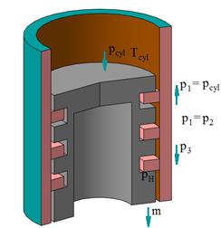
Fig. 7. Case 6 of the
positional relationship of the rings in the grooves of the piston, when ![]() ,
, ![]() and
and ![]() with
with ![]() ,
, ![]() =
=![]() and
and ![]() =
=![]()
Then ![]() is determined by the Formula (14) with m = 3,
is determined by the Formula (14) with m = 3, ![]() =
=![]() .
.
For further analysis, it
is convenient to consider the relative magnitude of gas escapes:
![]() (23)
(23)
where m is current gas escape in the crank angle [kg]; ![]() is total gas
escape per cycle [kg].
is total gas
escape per cycle [kg].
3. THE RESULTS OF THE
CALCULATIONS
The dependencies ![]() and
and ![]() for the diesel
with the main initial data are shown in Fig. 8 and 9:
for the diesel
with the main initial data are shown in Fig. 8 and 9:
-
engine power Nе = 155 kW
-
engine speed n = 2600 min-1
-
value of flow section ![]() = 0.3ˑ10-6 m2
= 0.3ˑ10-6 m2
-
volume on lands and the piston ring grooves: ![]() = 1.73ˑ10-6
m3
= 1.73ˑ10-6
m3
The initial and boundary
conditions were set according to the results of indexing and thermometry of the
diesel engine at the rated duty; discharge coefficient ![]() =0.85.
=0.85.
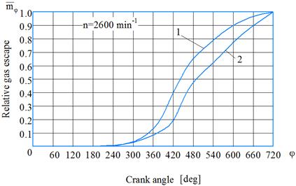
Fig. 8. Changes of the
relative gas escape ![]() depending on
the crank angle (n = 2600 min-1) subject to: 1 – the movement
of the rings in the grooves; 2 – the fixed rings
depending on
the crank angle (n = 2600 min-1) subject to: 1 – the movement
of the rings in the grooves; 2 – the fixed rings
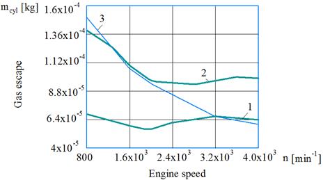
Fig. 9. Changes of the gas
escape ![]() depending on the
engine speed: 1 – idling conditions;
depending on the
engine speed: 1 – idling conditions;
2 – load conditions; 3
– the fixed rings
Movements of the rings in the
grooves noticeably affect the gas escape into the crankcase, especially when
the pressure in the cylinders is the biggest, that is, at 360-660o
crank angle (Fig. 8). After 660o crank angle, the difference in gas
escape values can be neglected.
The analysis of dependences ![]() confirms the
significant influence of the dynamics of rings on the course of cyclic gas
escape curves (Fig. 9). The deterioration of the sealing properties of the
piston rings with increasing the engine speed was noted earlier in other
studies [21,22].
confirms the
significant influence of the dynamics of rings on the course of cyclic gas
escape curves (Fig. 9). The deterioration of the sealing properties of the
piston rings with increasing the engine speed was noted earlier in other
studies [21,22].
This fact especially manifests
itself in idling modes due to the reduced pressure in the combustion chamber.
Thus, according to the gas
escape flow nature dependence on the engine speed, it is possible to assess the
compression ability of the diesel ring seal, the quality operation of the piston
rings. This enables
the determining of the technical condition of the CPG
parts which is especially important for mining industry trucks.
4. CONCLUSIONS
1. The effect of
the axial movement of the piston rings in the piston grooves on the blow-by in
the ICE was established. This creates
prerequisites for a more accurate assessment of their sealing ability and the
search for ways to further improve them.
2. The calculated
dependences to compute
the blow-by depending on the positional relationship of the rings in the piston
grooves was obtained
3. The dependencies of the gas escapes on the engine
speed allow judging upon the dynamic stability of the ring seal and solving the
issues of evaluating the technical condition of the CPG parts and improving
their operational properties, especially for idling modes.
Acknowledgements
The authors would like to express their gratitude to the referees for their
constructive and valuable suggestions.
References
1.
Abramchuk F., O. Grytsyuk, A. Prokhorenko, I.
Reveliuk. 2018. “Specifying the procedure for designing the elements of the
crankshaft system for a small high-speed diesel engine”. Eastern-European Journal of Enterprise
Technologies 3/1(93): 60-66. DOI: 10.15587/1729-4061.2018.133353.
2.
Akimov
O.G., V.I. Gusau, A.P. Marchenko. 2015.
“Обзор
компьютерно-интегрированных
систем и
технологий
изготовления
поршней двигателей
внутреннего
сгорания”. Восточно-Европейский
журнал
передовых
технологий. [In Russia: “Overview of computer-integrated systems and technologies
for manufacturing pistons of internal combustion engines”. East European Journal of Advanced
Technologies 6/1(78): 35-42. DOI: 10.15587/1729-4061.2015.56318. ISSN 1729-3774].
3.
Czech P.
2012. “Determination of the course of
pressure in an internal combustion engine cylinder with the use of vibration
effects and radial basis function - preliminary research”. TELEMATICS IN
THE TRANSPORT ENVIRONMENT. Edited by: Mikulski J. Book Series: Communications
in Computer and Information Science. Vol.: 329. P. 175-182. Conference: 12th
International Conference on Transport Systems Telematics, Katowice Ustron,
Poland, Oct 10-13, 2012.
4.
Czech P.
2011. “Diagnosing of disturbances in the
ignition system by vibroacoustic signals and radial basis function -
preliminary research”. MODERN TRANSPORT TELEMATICS. Edited by: Mikulski
J. Book Series: Communications in Computer and Information Science. Vol.: 239.
P. 110-117. Conference: 11th International Conference on Transport Systems
Telematics, Katowice Ustron, Poland, Oct 19-22, 2011.
5.
Figlus T., M. Stanczyk. 2016. “A method for detecting damage
to rolling bearings in toothed gears of processing lines”. Metalurgija 55(1): 75-78. ISSN: 0543-5846.
6.
Figlus T., M. Stanczyk. 2014. “Diagnosis of the wear of
gears in the gearbox using the wavelet packet transform”. Metalurgija 53(4):
673-676. ISSN: 0543-5846.
7.
Homišin
J. 2016. “Characteristics of
pneumatic tuners of torsional oscillation as a result of patent activity”. Acta
Mechanica et Automatika 10(4): 316-323. ISSN 1898-4088.
8.
Homišin
J., R. Grega, P. Kaššay, G. Fedorko, V. Molnár. 2019.
“Removal of systematic failure of belt
conveyor drive by reducing vibrations”.
Engineering
Failure Analysis 99: 192-202. ISSN 1350-6307.
9.
Iwnicki S. (editor). 2006. Handbook of Vehicle Dynamics. (Powertrain
and Transport). London, New York: Taylor & Francis Group. LLC.
10.
Kuľka J., M. Mantič, M. Kopas, E. Faltinová. 2017. ”Necessity
of wire rope replacement in crane lifting equipment after change of crane
operational parameters”.
Advances in Science
and Technology Research Journal 11: 226-230. DOI: 10.12913/22998624/71180. ISSN 2299-8624.
11.
Lyubarskyy P., D. Bartel.
2016. “2D CFD-model of the piston assembly in a diesel engine for the
analysis of piston ring dynamics, mass transport and friction”. Tribology International 104:
352-368. DOI: https://doi.org/10.1016/j.triboint.2016.09.017.
12.
Ma W., N. Biboulet, A.A. Lubrecht. 2018. “Performance evolution of a
worn piston ring”. Tribology International 126:
317-323. https://doi.org/10.1016/j.triboint.2018.05.028.
13.
Mohamed E.S. 2018. “Performance
analysis and condition monitoring of ICE piston-ring based on combustion and
thermal characteristics”. Applied Thermal
Engineering 132: 824-840. DOI: https://doi.org/10.1016/j.applthermaleng.2017.12.111.
14.
Notay R.S., M. Priest,
M.F. Fox.
2019. “The influence of lubricant
degradation on measured piston ring film thickness in a fired gasoline
reciprocating engine”. Tribology International 129:
112-123. DOI: https://doi.org/10.1016/j.triboint.2018.07.002.
15.
Postrzednik S., Z. Żmudka,
G. Przybyła. 2013. “Influence of the exhaust gas recirculation on
the oxygen contents and its excess ratio in the engine combustion
chamber”. Journal of KONES.
Powertrain and Transport 20 (3): 315-321.
16.
Sapietova
A., V. Dekys. 2016. „Use od Msc. Adams software product in modeling
vibration sources”. Komunikacie
1a(101): 101-107. ISSN: 2585-7878.
17.
Shen C., M.M. Khonsari.
2016. “The effect of laser machined
pockets on the lubrication of piston ring prototypes”. Tribology International 101:
273-283. DOI: https://doi.org/10.1016/j.triboint.2016.04.009.
18. Smutny J., V. Nohal, D. Vukusicova, H.
Seelmann. 2018. “Vibration analysis by the Wigner-Ville transformation
method”. Komunikacie 4. ISSN:
1335-4205.
19.
Söderfjäll M., A. Almqvist,
R. Larsson.
2016. “Component test for simulation of
piston ring – cylinder liner friction at realistic
speeds”. Tribology International 104: 57-63. DOI: https://doi.org/10.1016/j.triboint.2016.08.021.
20.
Tomazic D. 2005. Emissions
control. Engine Technology International (ETI) 01.
21.
Usman A., C.W. Park.
2016. “Optimizing the tribological
performance of textured piston ring–liner contact for reduced frictional
losses in SI engine: warm operating conditions”. Tribology International 99: 224-236. DOI: https://doi.org/10.1016/j.triboint.2016.03.030.
22.
Wong V.W., Simon C. Tung.
2016. “Overview of automotive engine friction and reduction
trends–effects of surface, material, and lubricant-additive
technologies”. Friction 4 (1): 1-28.
23.
Zapoměl
J., V. Dekýš, P. Ferfecki, A. Sapietová, M. Sága, M.
Žmindák. 2015. „Identification of material damping of a carbon composite
bar and study of its effect on attenuation of its transient lateral vibrations”. Journal of
Applied Mechanics 7(6). DOI:
https://doi.org/10.1142/S1758825115500817.
24.
Žuľová L., R.
Grega, J. Krajňák, G. Fedorko, V. Molnár. 2017. “Optimization of noisiness of mechanical system by using a
pneumatic tuner during a failure of piston machine”. Engineering
Failure Analysis 79: 845-851. ISSN 1350-6307.
Received 19.05.2019; accepted in revised form 11.08.2019
![]()
Scientific
Journal of Silesian University of Technology. Series Transport is licensed
under a Creative Commons Attribution 4.0 International License