Article citation information:
Juzek, M., Wojnar, G. Analysis of selected solutions and methods to limit the uneven load distribution on the tooth width. Scientific Journal of Silesian University of Technology. Series Transport. 2017, 96, 71-79. ISSN: 0209-3324. DOI: https://doi.org/10.20858/sjsutst.2017.96.7.
Michał
JUZEK[1], Grzegorz WOJNAR[2]
ANALYSIS
OF SELECTED SOLUTIONS AND METHODS TO LIMIT THE UNEVEN LOAD DISTRIBUTION ON THE
TOOTH WIDTH
Summary.
This article is dedicated to the subject of gearboxes, with a specific focus on
the load distribution on the tooth. The aim of the study was to review the
selected solutions and methods that can contribute to aligning the load on the
width of the tooth. The structure and operation of each solution are described
in detail. The paper presents the possible benefits of using the described
solutions.
Keywords:
gear wheel; contact stress; load distribution
1. INTRODUCTION
Due to the
numerous advantages involved, gear transmissions are used in most current drive
systems. Gears can be used in a wide range of applications, such as land
vehicles, marine propulsion systems, aviation engines or machinery drives in
technological processes. Regardless of purpose, the gearboxes should be
characterized by high reliability and durability. A very important factor
influencing the previously mentioned characteristics of transmission is load
distribution over the tooth width, which occurs during the transmission
operation. Any unevenness of the load along the teeth contact line contributes
to a local increase in transmission load, which results in the deterioration of
its durability and carrying capacity. The article reviews the innovative
construction solutions aimed at counteracting the effects of an uneven load on
the tooth width [1, 2, 3, 5].
2. LOAD DISTRIBUTION ON THE WIDTH OF THE
TOOTH AND ITS IRREGULARITY
Under real operating conditions, the
load distribution along the teeth contact line is not even, while the
accompanying contact stresses are the main factors that determine the
durability of transmission. In order to equalize the load distribution on the
width of the meshing, a modification of the tooth trace direction can be used.
Unfortunately, there are also
numerous difficult-to-avoid factors that influence the load distribution along
the teeth contact line, resulting in increased contact stress and the uneven
distribution of load on the tooth width [1, 3, 4, 5, 8]. According to [3, 5],
the factors influencing the load distribution on the tooth’s width can be
classified as follows:
-
geometry
of meshing
-
meshing
deviations
-
deviations
of the buildings caused by deviations of the axle position
-
internal
bearing clearance
-
the
process of lapping the gear unit
-
misalignment
and parallelism of transmission shafts
-
stiffness
of the wheels (teeth and hub), shafts, bearings, transmission and its
foundation
-
compensating
structural means
-
additional
shaft load (e.g., pulley)
As a measure of the unevenness of
the load on the width of the meshing, the coefficient of unevenness of the load
distribution K can be defined. Factor
K is determined as the ratio of the
local maximum tooth load per unit length to the mean value of load, which is
calculated assuming an even load distribution. The value of the coefficient K can be calculated from the following
relation, as reported in [1]:
![]() (1)
(1)
where:
pmax – maximum load per unit of wheel
width
pm – average load per unit of wheel
width
fmax – maximal local deformation of the
tooth
fm – average tooth deformation on
wheel width
The main determinant of the
distribution of the load on the tooth width is the resulting deviation of the
teeth contact line in the plane of action Fβy.
Fβy deviation is
defined as the distance of the sides of the teeth that cooperate in the frontal
direction. Its measurement is made in the situation of entering into meshing of
cooperating pairs of teeth. The value of deviation Fβy can be determined on the basis of the relation
shown in [3]:
![]() (2)
(2)
where:
Fβx – initial contact line deviation
without taking lapping into account
yβ – a lapping value that decreases
the initial deviation of the contact line as a result of lapping teeth during
the operation
3. REVIEW AND ANALYSIS OF SELECTED
STRUCTURAL SOLUTIONS TO REDUCE THE IRREGULARITY OF LOAD DISTRIBUTION ON TOOTH
WIDTH
Appropriate
structural solutions may be used to reduce undesirable effects of uneven load
distribution on the width of the tooth. The following section presents and
describes innovative solutions for reducing the adverse effects of the uneven
distribution of load.
3.1. Divided satellite
gear wheels of planetary transmission
In planetary gearboxes, the satellite wheels work with
the sun gear and internally toothed wheel. Often the sun wheel and satellites
have a relative wide width, due to considerable surface pressures between the
cooperating teeth. For fixing satellites on the journal axes, two bearings
(ball or roller) are most commonly used. Such a way of settling the wheels and
their considerable wide width, despite the high degree of performance and
assembly of the transmission, contribute to the uneven load distribution on the
width of the tooth. In order to reduce this unevenness, an innovative design of
satellite wheels was proposed in [9]. These solutions consist of dividing one
wide satellite wheel in a plane perpendicular to its axis of rotation into a
few narrower separate wheels. The total width of the newly formed wheels is the
same as the width of a single wide wheel. In addition, one oscillating bearing
on each of the narrower wheels is used. Such bearing independence and the additional
possibility of tilting the wheel significantly increase its give and allow a
more favourable load distribution on the tooth width [7, 9].
Fig. 1. Diagram of a portion of a satellite wheel with
bearing. Description of indications:
1) toothed ring of the classic wheel; 2-3) toothed rings of narrower wheels
formed;
4) bearings; 5) self-adjustable bearings; 6) journal of the satellite wheels
[7]
3.2. Oscillating wheel setting on the shaft using four
cylinders
A solution to limit uneven load distribution on tooth widths can be found in the patent (PL 379605). This patent contains an application of a constructional solution consisting of a pivotally connected shaft journal with a hub. Four cylinders are arranged perpendicular to the axis of rotation of the shaft. They are placed in the holes on the surface of the journal at 90° intervals. The other end of each cylinder is located in the groove on the inner surface of the hub. The hub grooves have a rectangular cross section and are parallel to the axis of rotation. The surface of the cylinder face, which is in the hub groove, is rounded by a radius. The length of the radius corresponds to the distance from the bottom of the groove to the axis of rotation of the journal. The proposed construction solution is designed to allow the wheel hub to tilt at an angle to the shaft journal on which it is mounted. This will increase wheel susceptibility, which in turn will improve the load distribution on its width [10].
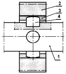
Fig. 2. Diagram of oscillating wheel setting on the
shaft, using four cylinders. Description of indications: 1) shaft’s journal; 2)
toothed gear; 3) groove with rectangular cross section;
4) cylinder [10]
For the above solution, a three-dimensional model has
been created. It shows the features of the analysed solution and simulates its
operation in different hub positions. For further consideration, an angle φ
was defined between the axes of the cross (obtained from the four cylinders
mentioned above) and their projection on the plane containing the shaft axis
and the gear axis. This plane is formed at a non-zero angle between the shaft
and gear axles.
It has been observed that, in the case of non-zero
angles between the axis of the shaft journal and the axis of the hub and the
non-zero values of the angle φ, there is overlapping of the side faces of
the rollers and the inner surface of the hub grooves. At a constant angle
between the shaft axis and the axis of the hub, this phenomenon reaches a
maximum value of φ = 45°. This phenomenon increases with the wheel hub
angle and is illustrated in Fig. 3. The presented situation can adversely
affect the durability of the joint and significantly accelerate the degradation
of the roll surfaces and hub grooves.
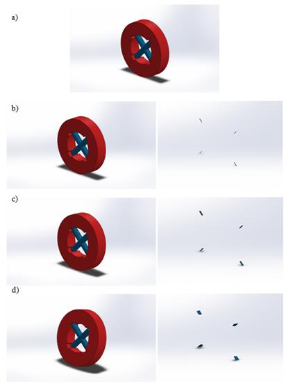
Fig. 3. Simulation of the hub oscillating operation:
a) three-dimensional model of the joint showing the main characteristics of the
analysed solution; b) the angle between the journal axis and the hub axis is
1°; c) the angle between the journal axis and the hub axis is 5°;
d) the angle between the journal axis and the hub axis is 15°
Figure 4 shows the overlapping volume of the side
rolls and the inner surface of the hub grooves Vk as a function of the angle
between the shaft rotation axis and the axis of the gear. In the illustrated
case, the diameter of the four-cross cylinder was 10 mm, the length of the two
cylinders was 60 mm and the diameter of the hole in hub was 52 mm.
Fig. 4. Overlapping
volume Vk diagram as a function of angle φ between the journal axis
and the hub axis
The
dimensionless coefficient of the overlapping volume Vk (Fig. 5) and the volume
of the crosspiece fragments, that is, the hub grooves Vf, were also proposed.
The Vk/Vf coefficients as a function of the angle between the axis of the shaft
journal and the axis of the hub φ are shown in Fig. 6.

Fig. 5. Fragments
of crosspieces in the hub grooves described as Vf

Fig. 6. Graph of
Vk/Vf ratio as a function of the angle of hub deflection φ
3.3. Eccentric setting of the shaft’s bearings
One method of limiting the uneven load distribution on
the tooth width, without interfering with wheel construction, is the eccentric
mounting of the shaft’s transmission bearings. Thanks to eccentric bearings, it
is possible to regulate the non-parallelism and misalignment of the
transmission axis, which also significantly affects the load distribution on
the width of the wheels mounted on the adjustable shafts. In addition, this
adjustability reduces the adverse impact of the elastic deformations of the
load-carrying elements and the deviations. The eccentric mounting of the shaft
bearings presented in [5] is particularly beneficial in the case of high-power
transmission with significant geometric dimensions. It is also worth
emphasizing that, compared to other solutions, this method does not
significantly increase the cost of transmission, but improves its strength
properties [5, 6].
3.4. Wheel construction with malleable elements
Patents US 2307129 [11] and US 307705 [12] illustrate
the construction of a gear, based on the separation of a cylindrical hub from a
toothed ring by use of an additional ring made of a malleable material. The
radius of the cylinder base was not accurately determined by the authors. The
ring can be one element or, as in the case of patent US 307705, two separate
and respectively narrower elements. The frictional force occurring on the
contact surface of the ring with the hub and the ratchet enables the transfer
of torque. In addition, in patent US 2307129, the authors applied two discs
attached to both side surfaces of the wheel by a screw connection. Discs are
designed to limit the excessive ring and wheel rim movements along the shaft
rotation axis. The use of a soft material in the toothed wheel structure allows
for a slight angular deviation in the rim, relative to the hub, which
translates into increased wheel give and can contribute to a more favourable
load distribution on its width.
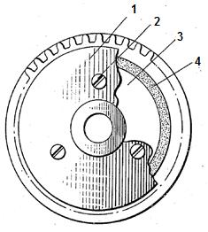
Fig. 7. Scheme of construction of wheel with a
malleable ring. Description of indications:
1) side discs; 2) screw connection; 3) wheel hub; 4) susceptible ring [11]
4. SUMMARY
Load distribution along the teeth
contact line occurring during the transmission operation is an important factor
affecting its durability. Due to the deviation in gear teeth manufacturing, the
transmission’s body and the elastic distortion of the shafts as a result of
inter-tooth force action, it is very difficult to obtain an even load
distribution under actual conditions. Any deviations cause an adverse increase
in contact stresses. The use of innovative gear designs or eccentric shaft
mounting, as described in the article, can contribute to a reduction in the
undesirable effects of uneven load distribution and significantly affect the
durability and reliability of the transmission. In addition, reducing the
unevenness of the load distribution on the width of the tooth also contribute
to a reduction in vibrations generated by the transmission and accompanying noise.
The article also presents an example of a structural
solution. Despite the relatively low cost of implementing this solution, which
is undoubtedly an important advantage, on the basis of the presented analysis,
it is stated that, in certain situations at work, there is a collision of
elements. For this reason, it is proposed to use this solution in terms of
relatively small values of uneven distribution of load on the width of the
meshing, rather than treat this solution, for example, as a method for equalizing
the load distribution when the transmission’s axes are non-parallel.
References
1.
Müller Ludwik.
1996. Przekładnie Zębate – Projektowanie.
[In Polish: Gears – Design.] Warsaw:
Wydawnictwa Naukowo-Techniczne. ISBN 83-204-1983-2.
2.
Müller Ludwik. 1986.
Przekładnie Zębate – Fynamika. [In
Polish: Gears – Dynamics.] Warsaw:
Wydawnictwa Naukowo-Techniczne. ISBN 83-204-0766-4.
3.
Łazarz Bogusław.
2001. Zidentyfikowany Model Dynamiczny
Przekładni Zębatej jako Podstawa Projektowania. [In Polish: Identified Dynamic Model of Toothed Gear as
the Design Basis.] Katowice-Radom: Wydawnictwo i Zakład Poligrafii
Instytutu Technologii Eksploatacji. ISBN 83-7204-249-7.
4.
Banaszek Jan,
Józef Jonak. 2008. Podstawy Konstrukcji
Maszyn – Wprowadzenie do Projektowania Przekładni Zębatych i Doboru Sprzęgieł
Mechanicznych. [In Polish: Fundamentals
of Machine Construction – An Introduction to the Design of Gears and the
Selection of Mechanical Couplings.] Lublin: Wydawnictwo Politechniki
Lubelskiej. ISBN 978-83-7497-042-6.
5.
Kochańczyk Marek.
2001. Metoda Wyrównania Rozkładu
Obciążenia kół Zębatych za Pomocą Mimośrodowego Psadzenia Łożysk. [In
Polish: Method of Equalizing the Load
Distribution of Gears by Eccentric Bearing Placement.] PhD thesis,
Katowice: Politechnika Śląska.
6.
Kochańczyk Marek,
Andrzej Wilk. 2002. “Wyrównanie
rozkładu obciążenia koła zębatego za pomocą mimośrodowego łożyskowania wału –
dobór cech geometrycznych.” [In Polish:
“Alignment of gear rack distribution by eccentric shaft bearings – selection of
geometric features”.] Szybkobieżne
Pojazdy Gąsienicowe 15(1): 1-7. ISSN 0860-8369.
7.
Filipowicz
Krzysztof. 2014. “Stanowisko badawcze do
wyznaczania wpływu dzielonych kół satelitów na obciążenie w zazębieniach
przekładni planetarnych”. [In Polish: “Research
station to determine the impact of split satellite wheels on planetary gear
engagement”.] Przegląd Mechaniczny
5: 29-34. ISSN 0033-2259.
8.
Zwolak Jan. 2012. “Wpływ nierównomiernego rozkładu obciążenia wzdłuż linii styku zębów na naprężenia kontaktowe.” [In
Polish: “Influence of uneven distribution of load along the tooth contact line
on contact stresses”.] Tribologia 5:
251-263. ISSN 0208-7774.
9.
PL 321717. Przekładnia Obiegowa. [In
Polish: Circulation Gear.] Kowal
Aleksander, Skoć Antoni, Spałek Jacek, Stachurski Jerzy, Suchoń Józef. 1 March
1999.
10.
PL 379605. Kształtowe Połączenie
Wahliwe Czopa z Piastą. [In Polish: Shaped
Swivel coupling Spindle with Hub.] Kowal Aleksander. 12 November 2007.
11.
US 2307129. Shockproof Gear. Barany Edmund, Hines
Earle G. 5 January 1943.
12.
US 307705. Stress Dissipation Gear and Method of Making
Same. P.J. Fenelon. 3 May 1994.
Received 09.05.2017; accepted in revised form 25.07.2017
![]()
Scientific Journal of Silesian
University of Technology. Series Transport is licensed under a Creative
Commons Attribution 4.0 International License